Choose a 3D Finger Joint Design Tool for Laser Cutting
The best 3D finger joint design tool for laser cutting lets you set material thickness, adjust kerf, preview the full assembly and export clean cutting paths. Choose a tool that matches your machine, sheet material and preferred design workflow.
On this page (12 sections)
- What makes a 3D finger joint design tool useful?
- Which joint options should the tool support?
- How should you compare browser tools and CAD software?
- Which design settings matter most for a fitted joint?
- How do you prepare a file before laser cutting?
- How should you test a 3D finger joint design?
- What should you use with laser marking products?
- Can a living hinge be part of a 3D laser design?
- Which export features should you check?
- How should you choose a tool for your experience level?
- What are the most common design mistakes?
- What is the final decision rule for a 3D finger joint design tool?
The best 3D finger joint design tool for laser cutting gives you control over material thickness, kerf, joint fit, assembly shape and export format. It should show how flat panels become a three-dimensional object before you spend material on a full cut.
A tool that only draws decorative lines is not enough for fitted joints. You need a workflow that turns real measurements into connected panels, then lets you correct the design after a small test cut.
What makes a 3D finger joint design tool useful?
A useful tool connects a flat drawing to a real assembly. It keeps key values visible so you can plan fit before cutting.
Look for these controls:
- Material thickness
- Kerf compensation
- Finger width and spacing
- Joint depth
- Panel dimensions
- Part labels
- Assembly preview
- Vector export
Material thickness matters most. A design for 3 mm sheet can fail if the real sheet differs.
For cut orientation, see which side of a material to laser cut. Review what kerf means in laser cutting before choosing a tool.
Does the tool apply kerf compensation?
A 3D finger joint design tool should let you enter a kerf value or adjust the joint clearance directly. If it has no way to account for the cut width, you may need to edit every panel manually in separate design software.
Kerf is not a universal number. It changes with the laser's focus, power, speed, material, thickness and cut direction.
Even different areas of one sheet can behave differently if the material is uneven.
Use the tool's value as a starting point, then cut a small calibration piece. A simple test can include several finger widths or a short box corner so you can compare loose, sliding and tight fits.
Can it show the complete three-dimensional assembly?
An assembly preview helps you catch errors before cutting. It can reveal a panel facing the wrong direction, a missing tab, a joint that overlaps another edge or a lid that has no clearance.
A flat layout cannot always show those problems. A panel may look correct from above but collide with a neighboring part after folding or joining.
Choose a tool that lets you inspect more than one angle. Zooming, rotating and hiding panels can make it easier to check inside corners and identify which edges need tabs or slots.
Which joint options should the tool support?
Choose a tool with more than one joint style if you will build different projects. Finger joints suit many box-like assemblies, while hook tabs, snap-fits and flexible sections solve other problems.
Start with our guide to joint types for laser cutting. It compares where finger joints, slots, tabs and other connections make sense.
A strong tool may include settings for:
- Straight finger joints
- Uneven finger spacing
- Edge tabs
- Slots
- Hook tabs
- Snap-fit connections
- Living hinge patterns
- Removable lids
- Dividers and internal supports
You do not need every option for a simple six-panel box. Clear defaults should give enough control to adjust fit without rebuilding the design.
When are finger joints the right choice?
Finger joints suit projects where flat panels meet at a regular angle and you want a visible mechanical connection. They can help align parts during assembly and give glue more edge area.
They are a good fit for boxes, trays, organizers, small cabinets, signs with depth and other polygonal assemblies. They are less suitable when the design needs a smooth outside surface, a hidden connection or a flexible bend.
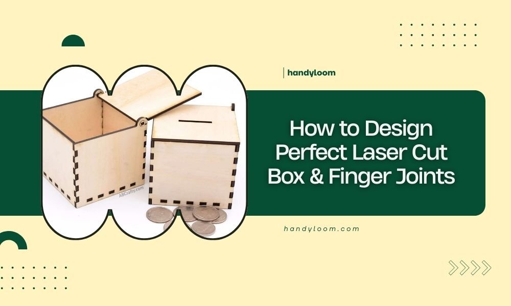
For a box-focused workflow, read how to design perfect laser cut box and finger joints. Use the design tool to adjust the dimensions, then verify the exported paths before cutting.
When should you use hook tabs or snap-fits?
Hook tabs hold panels with a locking shape. They help when the assembly must resist sliding in one direction.
Learn more about hook tab connections for laser cutting for structures that need to lock during assembly.
Snap-fits suit projects that go together without glue. They need careful clearance, since a tight joint can break during assembly.
Our guide to snap-fit joints for laser cutting covers fit, flexibility and repeated assembly.
How should you compare browser tools and CAD software?
A browser-based tool is often the quickest choice for a simple 3D finger joint design. Desktop CAD software is usually better when you need parametric edits, irregular shapes or a reusable design library.
For inlay layouts, compare laser marquetry software options.
Browser-based tools
Browser tools can work well when you want to enter a few measurements and receive a ready-to-export layout. They reduce setup time and may include built-in box templates.
Check whether the tool lets you save or download the source design. An export-only workflow can become limiting when you need to change one panel, alter the finger spacing or add a divider later.
Also check the output format. Your laser workflow may need SVG, DXF or another vector format.
A tool that exports only an image is not suitable for direct cutting.
Desktop CAD and parametric tools
Desktop software is a better fit for repeated projects and custom assemblies. Parameters can let you change the box width, depth, height or material thickness while keeping the joints connected.
This approach takes longer to learn. It also gives you more chances to create duplicate lines, open paths, overlapping geometry or construction marks that should not be cut.
Inspect the file before sending it to the laser. Confirm that cut lines, score lines and engraving lines are separated and assigned correctly.
Plug-ins and generators
A plug-in or generator can be useful when it creates standard joints inside software you already use. It may save time when you build many boxes with similar construction.
Check how it handles internal corners, part labels and kerf. A generator that creates attractive layouts but gives you no control over fit will still require manual repair.
Which design settings matter most for a fitted joint?
The most important settings are the measured sheet thickness, tested kerf, joint clearance, finger width and edge placement. These values affect whether the finished parts slide together, hold firmly or fail during assembly.
Material thickness
Measure the sheet with calipers in several places. Nominal thickness can differ from the actual thickness, especially with plywood, veneered board and materials that have compressed or uneven layers.
Enter the measured value when the tool allows it. If the design uses the label value instead, make a small test before cutting the final parts.
Kerf
Use a test piece to estimate the material removed by your laser. The result should represent the same material, thickness and cutting settings used for the project.
Some tools use a single kerf value for the whole design. Others let you adjust clearance or offset individual edges.
Either approach can work if the value is easy to change and the effect is visible in the preview.
Joint clearance
Clearance controls how easily one part enters another. A very tight joint may look precise but can split thin material during assembly.
A loose joint may need glue or create a crooked corner.
Choose the fit based on the project. A display box may favor a clean, snug fit, while a piece designed for repeated assembly may need more clearance.
Finger width and spacing
Finger width affects both appearance and strength. Very narrow fingers can be fragile, while very wide fingers may look heavy and reduce the number of useful contact points.
Keep the spacing consistent unless the design needs a special corner. The tool should help you avoid a tiny partial finger at the end of an edge.
Edge offsets
A finger joint needs enough material around each cut. Check the distance from the joint to the outside edge, nearby holes, engraved marks and other cuts.
Thin walls can split or burn more easily when several cuts meet. A preview helps, but a small physical test is still useful for delicate layouts.
How do you prepare a file before laser cutting?
Prepare the file by checking dimensions, closed paths, line types, scale and orientation. A clean export cuts the risk of wrong size cuts or duplicate paths.
Use this short review:
- Confirm the document units.
- Check the final panel dimensions.
- Verify material thickness and kerf value.
- Inspect every corner in the assembly preview.
- Remove duplicate lines.
- Confirm paths are closed where required.
- Separate cutting, scoring and engraving.
- Check labels and construction marks will not be cut.
- Place parts within the usable work area.
- Export a vector file at full scale.
Open the exported file in your laser software. Importing can change scale, units or line colors.
Should you add labels to the parts?
Labels can reduce assembly mistakes, especially when several panels look similar. Place them in an area that will remain visible or mark the parts with light engraving if your workflow supports it.
Use short labels such as A1, A2, B1 and B2. Match them to a simple assembly diagram or notes.
Avoid putting labels across joint edges. A mark that overlaps a tab or slot can change the fit or make the edge harder to inspect.
How should you test a 3D finger joint design?
Test one corner or a small section before cutting the full assembly. This checks the real fit without wasting an entire sheet.
A useful test includes:
- The same material as the final project
- The same material thickness
- The same laser settings
- The same joint style
- Several clearance values
- At least one inside corner
Measure the result and record whether it is loose, sliding, tight or unusable.
If the fit is wrong, change one variable at a time. Changing kerf, clearance and thickness together hides which change solved the problem.
For repeated work, keep tested settings by material and thickness. Recheck them when the material source or laser settings change.
What should you use with laser marking products?
Laser marking spray is a separate finishing material for metal marking, not a joint-design aid for wood or sheet assembly. It should not influence your choice of a 3D finger joint design tool.
The OMTech product is a 13 fl oz aerosol can for black marking on bare metals. It suits CO2 lasers at 25W and above, or fiber lasers for more vivid designs.
It appears white at first and turns black after engraving. Stated metals include aluminum, stainless steel and brass.
The spray dries in under 5 minutes, or 2 minutes with a hot air blower, and excess spray rinses away.
These details apply only to metal marking after design work. They do not replace kerf testing, joint previews or vector preparation.
Bathworks EZ-Etch is a 16 fl oz liquid used before refinishing. It is not a paint, coating or standalone repair, and does not change surface color by itself.
It chemically etches smooth, glossy, non-porous surfaces so a refinishing coating can bond. Listed materials are porcelain, ceramic, cast iron, tile and steel.
Acrylic, fiberglass and glass are not recommended.
Use requires cleaning, application, dwell time, thorough rinsing and drying before coating. It contains an acidic etchant, so wear chemical-resistant gloves and eye protection and ventilate the area.
Can a living hinge be part of a 3D laser design?
A living hinge turns a flat sheet into a bendable form. It needs a different pattern from a finger joint, with the hinge treated as a flexible section.
Read Mastering Laser Cut Living Hinges: Design & Settings if your project needs a bend instead of a rigid connection. Check material, grain direction, hinge spacing and bend radius, since thin repeated cuts can weaken a sheet.
A living hinge may suit a folding lid, flexible cover or curved form. It is not a replacement for a rigid finger joint when the assembly must hold a fixed angle.
Which export features should you check?
Choose a tool that exports full-scale vector geometry and preserves the distinction between cut, score and engrave paths. The file should open cleanly in your laser software without a full redraw.
Useful export checks include:
- Full-scale output
- Clear units
- Closed cutting paths
- Separate line types
- No duplicate geometry
- No hidden construction lines
- Editable source file
- Part labels outside cut paths
- Consistent line colors or layers
If the tool exports only a flattened image, it suits visual planning rather than direct fabrication. Another program will be needed for machine-ready paths.
Also check whether the tool preserves assembly relationships after export. Separate panels without a useful source file make later edits slower.
How should you choose a tool for your experience level?
Beginners should choose a tool with clear material, kerf and panel settings, plus an assembly preview. Experienced users may prefer parametric controls, scripting, reusable templates and more control over unusual joints.
For a first box
Choose a simple generator if you are making one small box from flat sheet stock. The tool should let you set width, depth, height, material thickness and kerf without requiring a long setup.
Use a basic finger pattern and test one corner. This gives you a clear way to learn how the digital values affect the physical fit.
For repeated production
Choose a parametric workflow if you will make many versions. Being able to change dimensions without redrawing every panel can reduce errors and make the design easier to maintain.
Add part labels and a repeatable test routine. A saved design is useful only when its assumptions remain clear.
For complex assemblies
Choose a tool that supports multiple joint styles, internal dividers, angled panels or non-rectangular parts. Review the preview from inside and outside the assembly.
Complex designs benefit from a staged process. Validate the outer shell first, then add dividers, lids, decorative cuts or flexible sections.
What are the most common design mistakes?
The most common mistakes are using nominal thickness, skipping kerf tests, trusting a flat layout, exporting at the wrong scale and ignoring assembly order.
A design can also fail when tabs are placed on the wrong edge. Mark the inside and outside faces before cutting, especially with an asymmetrical pattern.
Another mistake is making fingers too narrow for the material. More fingers do not always create a better joint if sections are weak or hard to cut cleanly.
Do not add a snap-fit, hook tab or living hinge just because the tool offers it. Choose the connection based on how the finished object must assemble, hold and move.
What is the final decision rule for a 3D finger joint design tool?
Choose a tool if it lets you enter measured material thickness, apply a tested kerf, preview the complete assembly and export clean vector paths.
Pick a simple browser generator for one-off boxes. Pick parametric desktop software for repeated designs or complex assemblies.
Pick a tool with multiple joint options when your work includes hook tabs, snap-fits or living hinges.
The right tool makes fit and assembly predictable. Test one joint first, correct the design, then cut the full project.
- How to Choose Joints for Laser Cut Wood
- How to Design Perfect Laser Cut Box & Finger Joints
- How to Design Hook Tab Connections for Laser Cutting
- How to Design Snap-Fit Joints for Laser Cutting
- Mastering Laser Cut Living Hinges: Design & Settings
- What Is Kerf in Laser Cutting?
Frequently asked questions
What should a 3D finger joint design tool include?
A useful 3D finger joint design tool should let you enter material thickness, set kerf compensation, choose joint dimensions, preview connected parts and export vector cutting paths. It should also make it easy to edit tab spacing, test clearances and label parts before sending the file to your laser software.
Does a 3D finger joint design tool replace kerf testing?
No. A 3D finger joint design tool can apply a kerf value, but your laser, lens, speed, power, focus and material all affect the final cut.
Make a small test comb or joint panel, measure the result, then update the tool's kerf setting before cutting a full assembly.
Can I use a 3D finger joint design tool for plywood boxes?
Yes, if the tool supports flat sheet construction and exports usable vector paths. Enter the real plywood thickness, account for kerf, check the grain direction and preview how each panel meets before cutting.
Plywood thickness can vary, so measure the sheet instead of relying only on its label.
Should I choose a browser tool or desktop software?
Choose a browser tool for quick box layouts and simple fitted joints when you want a short setup. Choose desktop CAD or parametric software when you need repeated edits, unusual angles, nested parts, assembly previews or a reusable design system.