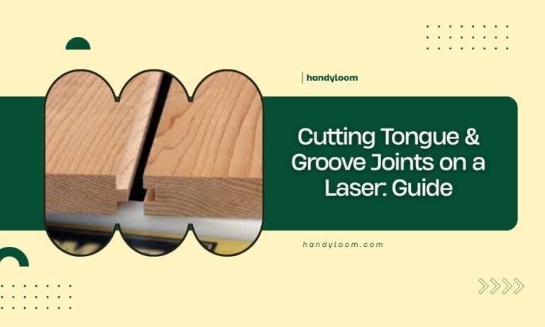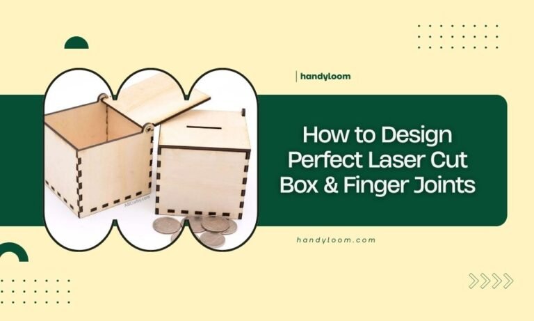
Perfect friction fit laser cut joints require precise kerf compensation and material consideration to create connections that hold firmly without glue or fasteners.
The key to successful friction fit joints lies in adjusting your laser settings and joint dimensions based on your material thickness and laser kerf width.
Understanding Friction Fit Joints
Friction fit joints work by creating a tight connection between two pieces. The joint relies on material compression and surface tension to stay together.
Think of it like forcing a cork into a wine bottle. The cork compresses slightly, creating pressure that keeps it in place. Your laser cut joints work the same way.
Why Friction Fits Matter for Makers
You save time and money with friction fits. No glue means no mess and no waiting for things to dry. No screws means no extra hardware costs.
These joints also look cleaner. Nothing disrupts the smooth lines of your project like visible fasteners or glue squeeze-out.
Essential Tools and Materials
You need a few basic items to get started with friction fit joints.
Laser Cutter Requirements
- CO2 laser cutter with consistent power output
- Air assist system for clean cuts
- Properly aligned mirrors and lens
- Reliable material hold-down system
Design Software Options
Most vector design programs work well. I found that Adobe Illustrator, Inkscape, and Fusion 360 all handle joint design effectively.
The software matters less than understanding how to design the joints themselves.
File Preparation Tips
Keep your cut lines as thin vectors. Use different colors for different cut depths if your project needs them.
Group related parts together. This helps when you need to adjust multiple joints at once.
Material Selection and Properties
Your material choice affects every aspect of joint performance. Different materials compress differently under pressure.
Best Materials for Friction Fits
| Material | Flexibility | Joint Tolerance | Best Use |
|---|---|---|---|
| Plywood | Medium | 0.1-0.2mm tight | Structural joints |
| MDF | Low | 0.05-0.1mm tight | Precise assemblies |
| Cardboard | High | 0.2-0.5mm tight | Prototypes |
| Acrylic | Very Low | 0.02-0.05mm tight | Display pieces |
Wood Grain Direction
Pay attention to grain direction in plywood. Joints cut across the grain hold better than those cut with it.
The cross-grain fibers resist compression more than parallel fibers. This creates stronger holding power.
Measuring Your Laser Kerf
Kerf width changes everything about your joint design. You must measure it for each material and thickness combination.
Simple Kerf Test Method
Cut a 20mm square from your material. Measure the actual size with calipers.
Subtract the measured size from 20mm, then divide by 4. This gives you the kerf width per side.
Recording Your Results
Keep a notebook with kerf measurements for different materials. Include laser power, speed, and material thickness.
I found this saves hours of test cuts later. You can reference your notes instead of starting from scratch each time.
Joint Design Fundamentals
Good joint design starts with understanding how the pieces will connect and move.
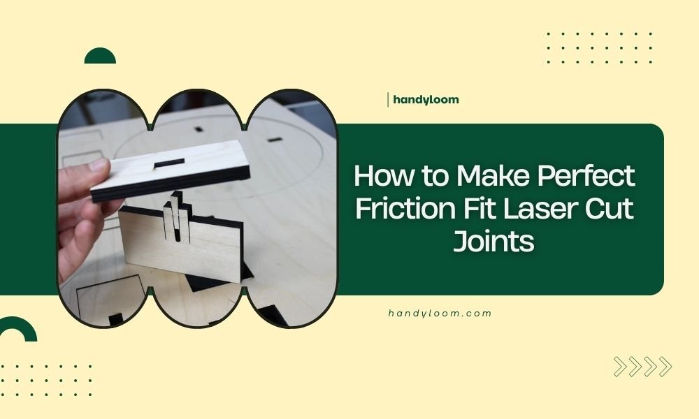
Tab and Slot Basics
The tab should be slightly larger than the slot. Start with your kerf width as the size difference.
For 3mm plywood with 0.1mm kerf, make your tab 0.1mm wider than the slot opening.
Length Considerations
Longer tabs hold better but become harder to insert. Keep tab length between 1.5 and 3 times the material thickness.
Short tabs pop out easily. Long tabs can crack the surrounding material when forced.
Finger Joint Variations
Multiple small tabs distribute stress better than one large tab. This prevents cracking and splitting.
Space your fingers evenly. Uneven spacing creates weak points that fail under stress.
Calculating Perfect Tolerances
Tolerance calculation involves your kerf width, material properties, and desired fit tightness.
Basic Tolerance Formula
Start with: Tab width = Slot width + Kerf width + Compression allowance
The compression allowance ranges from 0.05mm for rigid materials to 0.3mm for flexible ones.
Testing Your Calculations
Cut test joints before committing to your full project. Make several with slightly different tolerances.
Number each test piece. This helps you track which tolerance works best for future projects.
Common Joint Types and Applications
Different joint styles work better for different applications and stress directions.
T-Joints for Perpendicular Connections
T-joints connect pieces at right angles. The vertical piece slots into the horizontal one.
Add small relief cuts at the slot corners. These prevent stress concentration that can cause cracks.
Reinforcing T-Joints
Consider adding small tabs on both sides of the main joint. This prevents the joint from working loose over time.
Box Joints for Strong Corners
Box joints create strong corner connections with multiple interlocking fingers.
Keep finger width between 0.5 and 2 times your material thickness. Thinner fingers look better but take longer to cut.
Box Joint Layout Tips
Start and end with the same piece type on all corners. This ensures your corners align properly.
Odd numbers of fingers often work better than even numbers for alignment.
Laser Settings Optimization
Your laser settings directly affect cut quality and joint fit.
Power and Speed Balance
Lower power with multiple passes often gives cleaner cuts than high power single passes.
I researched various laser cutting studies and found that multiple passes reduce heat buildup and material warping.
Air Assist Importance
Good air assist removes debris and prevents flame polishing on cut edges.
Flame polished edges are too smooth for good friction fits. You need some surface texture for grip.
Focus Point Adjustment
Focus slightly below the material surface for cleaner bottom edges. This improves joint fit.
Top edge quality matters less for joints than bottom edge precision.
Testing and Troubleshooting
Even perfect calculations sometimes need adjustment. Testing helps you fine-tune your approach.
Too Tight Joints
Joints that require excessive force to assemble will eventually break something.
Reduce your tab size by 0.02-0.05mm increments until assembly becomes manageable.
Emergency Loosening Techniques
Light sanding on tab edges can salvage over-tight joints. Use fine grit paper and work slowly.
Sand both sides evenly to maintain joint symmetry.
Too Loose Joints
Loose joints defeat the purpose of friction fit connections.
Add thin tape strips to tab surfaces as a quick fix. For permanent solutions, remake the parts with tighter tolerances.
Assembly Tips and Techniques
Proper assembly technique prevents damage and ensures strong joints.
Insertion Methods
Insert tabs straight and square. Angled insertion can damage the slot edges.
Use steady pressure rather than sudden force. Let the material compress gradually.
Assembly Order Planning
Plan your assembly sequence before cutting. Some joint arrangements only work with specific assembly orders.
Draw assembly diagrams if your project is complex. This prevents confusion later.
Advanced Joint Modifications
Simple modifications can improve joint performance for specific applications.
Tapered Entries
Small chamfers on tab leading edges make insertion easier without weakening the joint.
Keep chamfers under 0.5mm deep. Larger chamfers reduce the friction surface area.
Locking Features
Small barbs or hooks on tabs create one-way joints that resist disassembly.
Use these carefully. They make permanent assemblies that cannot be easily repaired.
Quality Control and Consistency
Consistent results require attention to your entire process chain.
Material Storage
Store materials flat and dry. Warped or damp materials create inconsistent cuts and poor joint fits.
Check material thickness with calipers before cutting. Thickness variations affect joint tolerances.
Machine Maintenance
Keep your laser optics clean and properly aligned. Dirty lenses create irregular kerfs.
Check belt tension regularly. Loose belts cause positioning errors that ruin joint precision.
Conclusion
Perfect friction fit laser cut joints come down to precise measurement, careful calculation, and thorough testing. Start with accurate kerf measurements for your specific material and laser combination. Calculate your tolerances based on material properties and desired fit tightness. Always cut test joints before committing to your final project.
Remember that small adjustments make big differences in joint performance. Keep detailed records of what works for different materials and applications. With practice, you will develop an intuitive feel for designing joints that assemble smoothly and hold securely. The time invested in perfecting your technique pays off in professional-looking projects that require no additional fasteners or adhesives.
How do I know if my friction fit joint is too tight?
Your joint is too tight if it requires excessive force to assemble, causes material cracking, or makes the surrounding material bulge. A properly fitted joint should require firm but reasonable pressure to connect.
Can I use friction fit joints with very thin materials like paper?
Paper and very thin materials work poorly for friction fits because they lack the structural strength to maintain compression. Consider using interlocking geometric designs or adhesive methods instead for materials under 0.5mm thick.
What should I do if my laser kerf varies across different areas of the bed?
Kerf variation usually indicates alignment issues with your laser optics or an unlevel cutting bed. Have your machine serviced to correct these problems, as consistent kerf width is essential for reliable joint fits.
How many times can I disassemble and reassemble friction fit joints?
Most wood-based materials handle 5-10 assembly cycles before joint surfaces wear smooth and lose holding power. Harder materials like acrylic may handle more cycles, while softer materials like cardboard typically allow fewer.
Should I seal or finish friction fit joints after assembly?
Apply finishes before assembly when possible, as finishing materials can change joint dimensions and reduce friction. If you must finish after assembly, use thin finishes and avoid heavy buildup in joint areas that might cause loosening.