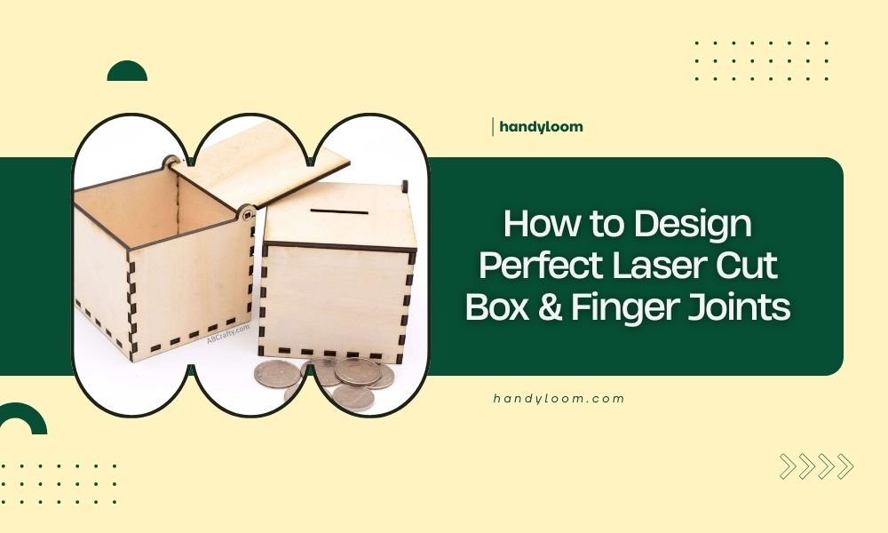
Perfect laser cut box finger joints require precise kerf compensation, proper material thickness calculations, and consistent spacing between fingers that’s typically 1.5 to 3 times your material thickness.
Your finger joint success depends on three key factors: accurate measurements, the right design software settings, and understanding how your specific laser cutter behaves with different materials.
Understanding Laser Cut Box Fundamentals
Laser cutting boxes sounds simple until you try it. The laser beam removes material as it cuts, creating a gap called kerf. This gap affects how your pieces fit together.
Most beginners skip kerf compensation and end up with loose, wobbly joints. You need to account for this material removal in your design phase, not after cutting.
What Makes Finger Joints Work
Finger joints interlock like puzzle pieces. One piece has protruding fingers, the other has matching slots. When done right, they create strong, attractive corners without glue or fasteners.
The magic happens when your fingers fit snugly. Too loose and your box falls apart. Too tight and you’ll crack the wood trying to assemble it.
Essential Design Software and Tools
You don’t need expensive software to design great finger joints. Several free options work perfectly for most projects.
Free Design Options
- Fusion 360 (free for personal use)
- Inkscape with box-making extensions
- Online box generators like MakerCase
- Tinkercad for simple designs
Professional Software Choices
If you’re serious about laser cutting, Adobe Illustrator or CorelDRAW offer more control. AutoCAD works well for precise technical drawings.
I found that most hobbyists get excellent results with free tools. Save money on software and invest in better materials instead.
Measuring Your Material Correctly
Accurate material thickness measurement is your foundation. Wood and acrylic often vary from their stated thickness.
Using Calipers for Precision
Digital calipers give you measurements to three decimal places. Measure in multiple spots because materials aren’t always uniform.
I researched common material variations and found that plywood can vary by 0.5mm or more across a single sheet. Always measure where you’ll actually cut.
Accounting for Material Variations
Even premium materials have thickness variations. Plan for this by testing small samples before cutting your final project.
Create test strips with different finger widths. This saves materials and prevents costly mistakes on large projects.
Calculating Kerf Compensation
Kerf varies by material, thickness, laser power, and cutting speed. You need to measure it for each material type you use.
Simple Kerf Testing Method
Cut a 100mm square from your material. Measure the actual size with calipers. The difference divided by four gives you kerf per side.
For finger joints, you typically compensate by adding half the kerf width to each finger and subtracting half from each slot.
Common Kerf Values by Material
| Material | Typical Kerf Range | Compensation Method |
|---|---|---|
| 3mm Plywood | 0.1-0.15mm | Add 0.05-0.075mm to fingers |
| 6mm Acrylic | 0.15-0.25mm | Add 0.075-0.125mm to fingers |
| 3mm MDF | 0.08-0.12mm | Add 0.04-0.06mm to fingers |
Designing Finger Joint Dimensions
Finger size affects both strength and appearance. Wider fingers look chunky but offer more gluing surface. Narrow fingers look elegant but may break easily.
The Golden Ratio for Finger Width
Most experts recommend finger widths between 1.5 and 3 times your material thickness. For 3mm plywood, fingers between 4.5mm and 9mm work well.
I found online that furniture makers often use the 2x rule. Double your material thickness for balanced strength and appearance.
Finger Spacing and Count
Odd numbers of fingers usually look better than even numbers. Start with the corner finger, then space evenly across your board width.
Your last finger should be roughly the same size as your first. Adjust spacing slightly to avoid tiny end fingers that break easily.
Planning Finger Layout
Divide your board width by your desired finger width. Round to the nearest odd number. Adjust finger width to fit perfectly.
Example: 100mm wide board with 8mm fingers = 12.5 fingers. Round to 13 fingers. New finger width = 100/13 = 7.7mm.
Creating Your First Box Design
Start simple. A basic rectangular box teaches all the essential skills without overwhelming complexity.
Box Component Planning
Every box needs four sides, a bottom, and optionally a top. Plan which edges get fingers and which get slots.
The standard approach puts fingers on the front/back pieces and slots on the side pieces. This creates clean corners with hidden end grain.
Drawing the Base Rectangle
Start with your interior dimensions. Add material thickness where needed. Your cutting lines define the outside edges of your pieces.
Double-check that opposite pieces are identical. Mistakes here multiply across all four corners.
Adding Fingers to Your Design
Draw fingers as rectangles extending beyond your base piece. Make slots by removing rectangles from the edge.
Keep fingers and slots consistent across matching pieces. Use copy and paste rather than redrawing to avoid tiny differences.
Advanced Joint Techniques
Once basic finger joints feel easy, try these variations for stronger or more attractive boxes.
Tapered Finger Joints
Slightly tapered fingers create self-tightening joints. Make the finger base 0.1mm wider than the tip.
This technique works especially well with softwoods that compress slightly during assembly.
Reinforcement Strategies
Add small corner brackets inside your box for extra strength. Laser cut these from thinner material.
Consider finger joint glue pockets – small recesses that hold extra adhesive without creating squeeze-out mess.
Common Design Mistakes to Avoid
Learning from others’ mistakes saves time and materials. These issues trip up most beginners.
Ignoring Grain Direction
Wood grain affects strength dramatically. Place fingers perpendicular to grain direction when possible.
Parallel grain fingers break easily, especially in thin materials. Plan your layout considering grain orientation.
Forgetting Assembly Order
Some box designs only assemble in specific sequences. Draw assembly diagrams before cutting.
Test assembly with cardboard mockups if you’re unsure. This catches design problems before wasting good materials.
Inadequate Test Cuts
Always cut test joints before committing to your final project. Material behavior varies more than you’d expect.
Make test pieces large enough to represent real assembly forces. Tiny test cuts don’t reveal assembly problems.
Testing and Refining Your Design
Perfect joints come from iterative testing. Each material and laser combination needs slightly different settings.
Creating Test Patterns
Design test strips with multiple finger sizes and kerf compensations. Cut several variations at once.
Label each test clearly. You’ll forget which settings produced which results faster than you think.
Evaluating Joint Quality
Good joints slide together with gentle hand pressure. You shouldn’t need hammers or excessive force.
Joints should hold firmly without glue but still allow disassembly if needed. This indicates proper kerf compensation.
Troubleshooting Common Problems
Even experienced makers encounter joint problems. Here’s how to diagnose and fix the most common issues.
Loose Joints
Loose joints usually mean insufficient kerf compensation. Increase finger dimensions by 0.02-0.05mm and test again.
Check your laser focus and cutting speed. Dull or misaligned beams create wider kerfs than expected.
Tight or Impossible Assembly
Overly tight joints risk cracking during assembly. Reduce finger dimensions slightly.
Sand lightly with fine grit paper if joints are almost right. Sometimes minor adjustment beats redesigning entirely.
Burn Marks and Rough Edges
Excessive burning indicates wrong cutting parameters. Increase speed or reduce power settings.
Masking tape protects surfaces during cutting. Remove it immediately after cutting to prevent residue buildup.
Conclusion
Designing perfect laser cut finger joints combines art and science. Start with accurate measurements, account for kerf, and test thoroughly before final cuts.
Remember that every laser and material combination behaves differently. Build a library of tested settings for your common materials. Your future self will thank you when projects go together perfectly on the first try.
The key to success lies in patience and systematic testing. Don’t rush the design phase – time invested here saves frustration later. With practice, you’ll develop an intuition for what works, making the whole process faster and more enjoyable.
How do I know if my kerf compensation is correct?
Test joints should slide together with moderate hand pressure and hold firmly without wiggling. If you need excessive force, reduce compensation. If joints feel loose, increase compensation by 0.02-0.05mm increments.
What’s the strongest finger joint configuration for heavy items?
Use finger widths 2.5-3 times your material thickness with additional corner reinforcement blocks. Consider adding a groove for the bottom panel that distributes weight across the entire joint rather than just the corners.
Can I use finger joints with curved or angled box sides?
Yes, but you’ll need to calculate compound angles carefully. Design software with 3D capabilities helps visualize these complex joints. Start with simple angles before attempting compound curves.
How thin can materials be while still supporting functional finger joints?
Materials thinner than 2mm become fragile for finger joints. Consider living hinges or tab-and-slot connections instead. If you must use thin materials, make fingers wider and reduce the number of joints per edge.
Should I pre-finish materials before laser cutting finger joints?
Pre-finishing can interfere with joint fit and glue adhesion. Cut first, then finish with careful masking around joint areas. If you must pre-finish, account for finish thickness in your kerf compensation calculations.